1. Characteristic of Z18 I H Beam Assembly and Tack Weld Machine:
1) Z18 Manual Alignment Manual Tack Welding H Beam Assembly Machine is brother product of previous Z15 model;
2) In this product section, we will discuss further on machine body and components in detail:
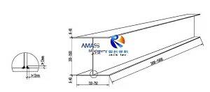
Finished assembled H Beam fit up from the machine: (Fig.1)
2. Top Gantry of Z Series I H Beam Assembly Machine: (Fig.2)
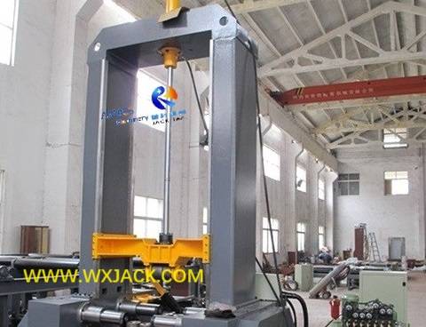
1) Sub Assemblies of Top Gantry in H Beam Assembly Machine:
As can be seen from above sketch, top gantry is an inversed U shape frame, installed on the machine bed of the Z series hydraulic H Beam Assembly and Tack Weld Machine;
2) Structure: The entire top gantry assembly is of welding structure, and assembled into shape in such error proof way: In its top beam there is a square hole made to receive a tenon and so to form a joint;
3) Assembly Accuracy Assurance: To fully guarantee precise alignment in the machine, there are four pieces of precise guideways fit on the left and right sides of internal surface of the two columns (Marked in red square in the above picture), making sure smooth, stable and precise movement of downward pressing unit in the machine (Marked in green square in the above picture);
4) Benefit: Such design of top gantry is same for both automatic (CO2 tack welding, as well as Web Flange fit together) and manual working mode machine with tack welding.
3. Downward Pressing Unit in H Beam Assembly Machine: (Fig.3)
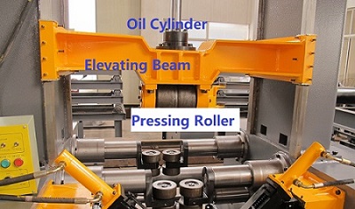
1) Usage: In operation of this Z series machine, this unit serves as positioning and holding function for assembling process;
2) Assembled Position: It is fit at internal of the top gantry, and travels along the above mentioned four pieces of precise guideways:
Downward pressing unit of Wuxi JACK machine: (Fig.4)
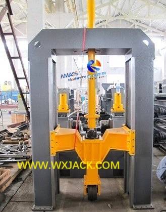
3) Main components of the downward pressing unit in the machine include elevating beam, downward pressing roller, and downward pressing oil cylinder (See above picture);
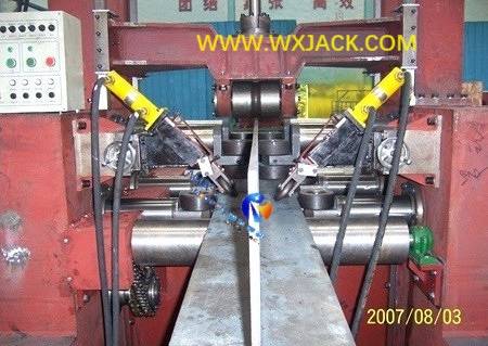
4) Characteristics: There is a circle of slot at middle of the downward pressing roller, for clipping with edge of H Beam web perfectly, during operation of these Z15/ Z18/ Z20 models machine with stitch welding (See below picture):
T Beam/ H Beam fit up in Wuxi JACK H I Beam Assembly Machine: (Fig.5)
5) Local zoom up of connecting section of the downward pressing unit onto guideways in the H Beam Assembling Machine: (Fig.6)
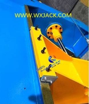
a) There is copper slice fit between the downward pressing unit and guideway, serving as cushion for vertical movement of the downward pressing unit, during working period of the machine. (Copper has good anti-abrasion performance);
b) The pieces of four bolts are used for adjusting clearance between the downward pressing unit and guideway, for best fitting in the machine;
6) As summary, with years of application practice and continuous improvement, structure and make up of these Z15/ Z18/ Z20 models H Beam Assembly Machine with Tack Welding grows more and more rational;
7) The Top Gantry and Downward Pressing Unit are “top sections” of the machine. In next section of Z20 manual model machine we will explore “bottom sections” of the machine — Bed and Pulling Rod System;
8) Supplementary Notes for Z series Manual Alignment Manual Tack Welding H Beam Assembly Machine:
a) For automatic assembly and manual assembly in the machine, please check product section of “Z20 Self Alignment Machine with Manual Tack Welding” and “Z15 Manual Alignment machine with Automatic Tack Welding”;
b) For CO2 tack welding in the machine, please check product section of “Z18 Self Alignment Machine with Automatic Tack Welding”.
4. Technical Parameters of Z18 Manual Alignment Manual Tack Welding H Beam Assembly Machine:
Model | Z18 Manual Alignment with Manual Tack Welding H Beam Assembly and Tack Weld Machine |
H Beam Web Height (mm) | 200 ~ 1,800 |
Fitting H Beam Web Thickness (mm) | 6 ∽ 32 |
Fitting H Beam Flange Width (mm) | 200 ∽ 800 |
Fitting H Beam Flange Thickness (mm) | 6 ∽ 40 |
Fitting H Beam Length (mm) | 4,000 ∽ 12,000 |
Input and Output Conveyor Length | 3 x 2,600 mm Each |
Max. H Beam Weight | 20 Ton. |
Web and Flange Alignment Style | Manual Alignment |
Tack Welding Style | Manual CO2 tack welding |
Operator | Two operators with proficient welding skill |
Conveyor speed (mm/min.) | 2000, constant |


